PRESSURIZATION
CONTROL SYSTEMS

description
& FEATURES
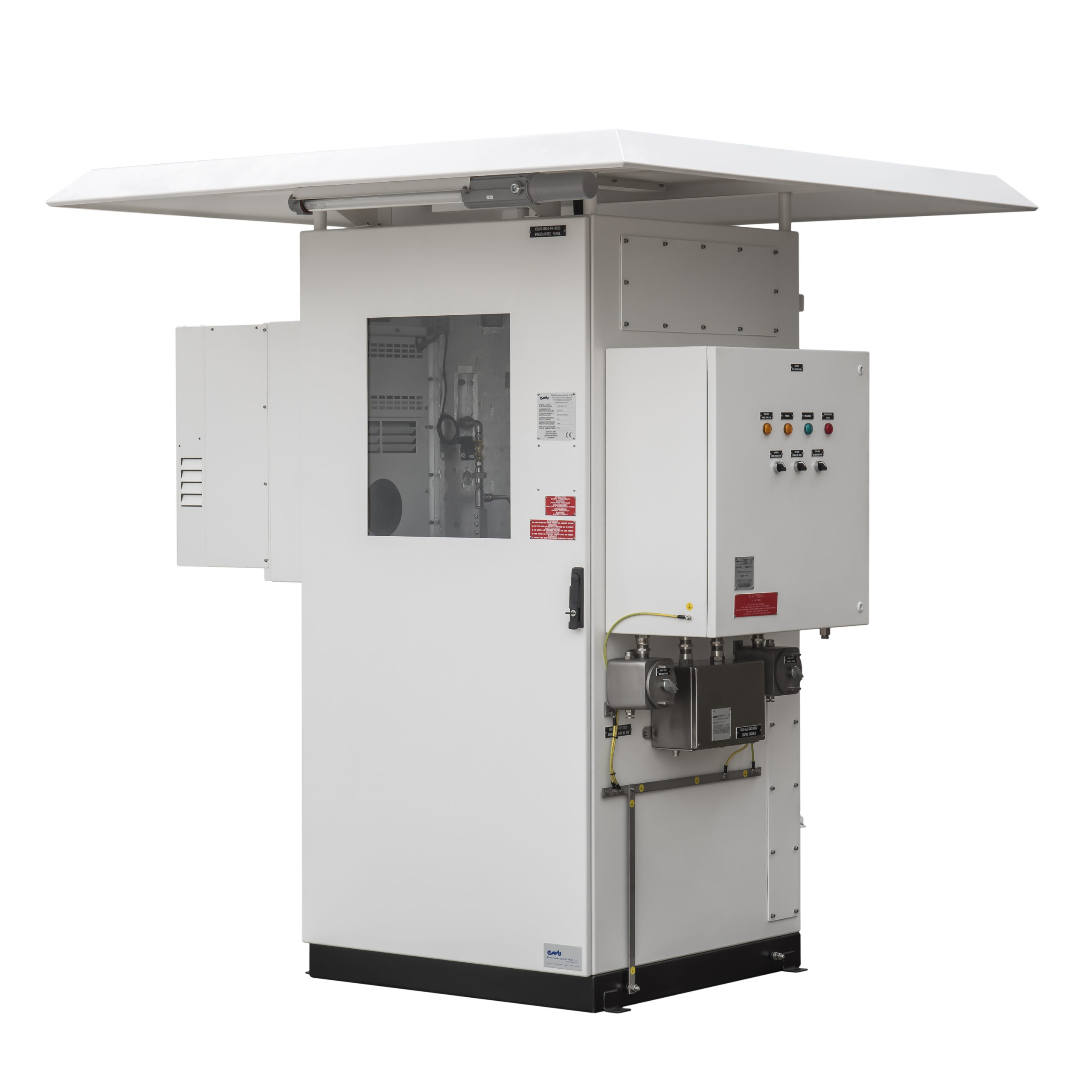
The MSP series, in the various types: MSP/A1, MSP/A2, MSP/M, etc. relates to Pressurization Control Systems, of Enclosures (Cabinets/Electro-instrumental Panels) explosion protected by means internal overpressure, type of protection “p”
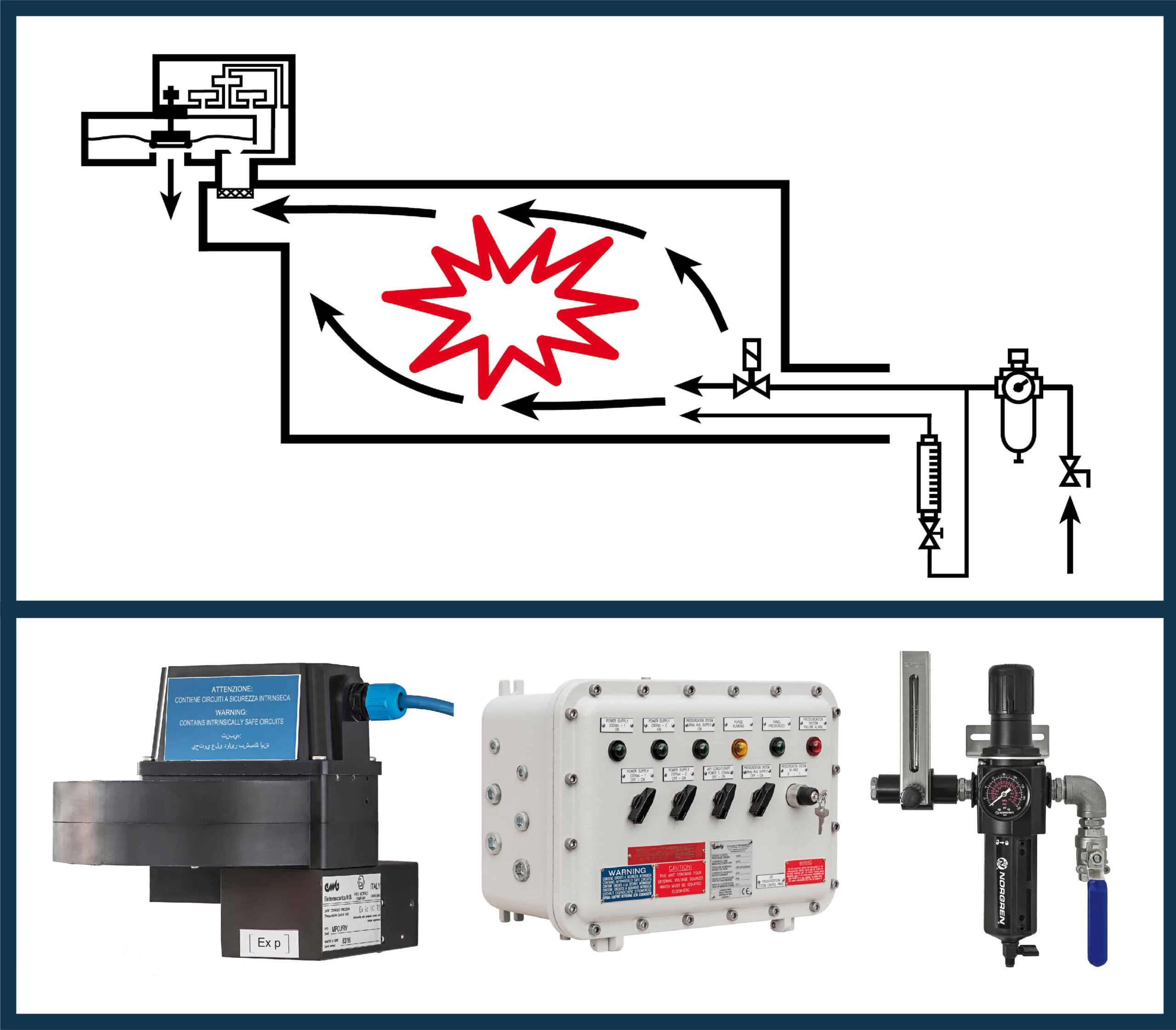
The fundamental criterion of this type of protection is the absolute need to secure the pressurized enclosure, by means of an appropriate “Purging” operation, before activating both the power supplies and any type of signal energized from the outside.
The system is also able to keep a protective gas inside the enclosure, after Purging, at a pressure higher than external atmosphere, in order to avoid the penetration of any explosive atmosphere
>> PURGING OPERATION
This operation consists in passing through the enclosure, for a predetermined time and with a predetermined flow rate, a quantity of protective gas, sufficient to eliminate any dangerous gas present inside the enclosure or in any case to bring its concentration to a safe level (≤ 25% of the LEL)
In particular, the MSP/A1 and MSP/A2 systems are integrated in the ATEX and IECEx certificates of our MAP series Pressurized Cabinets (“Ex ib pzc” or “Ex ib pxb” type of protection) and can manage not only the Pressurization with protective gas leakage compensation, but also the dilution of any limited release of gas, from internal source.
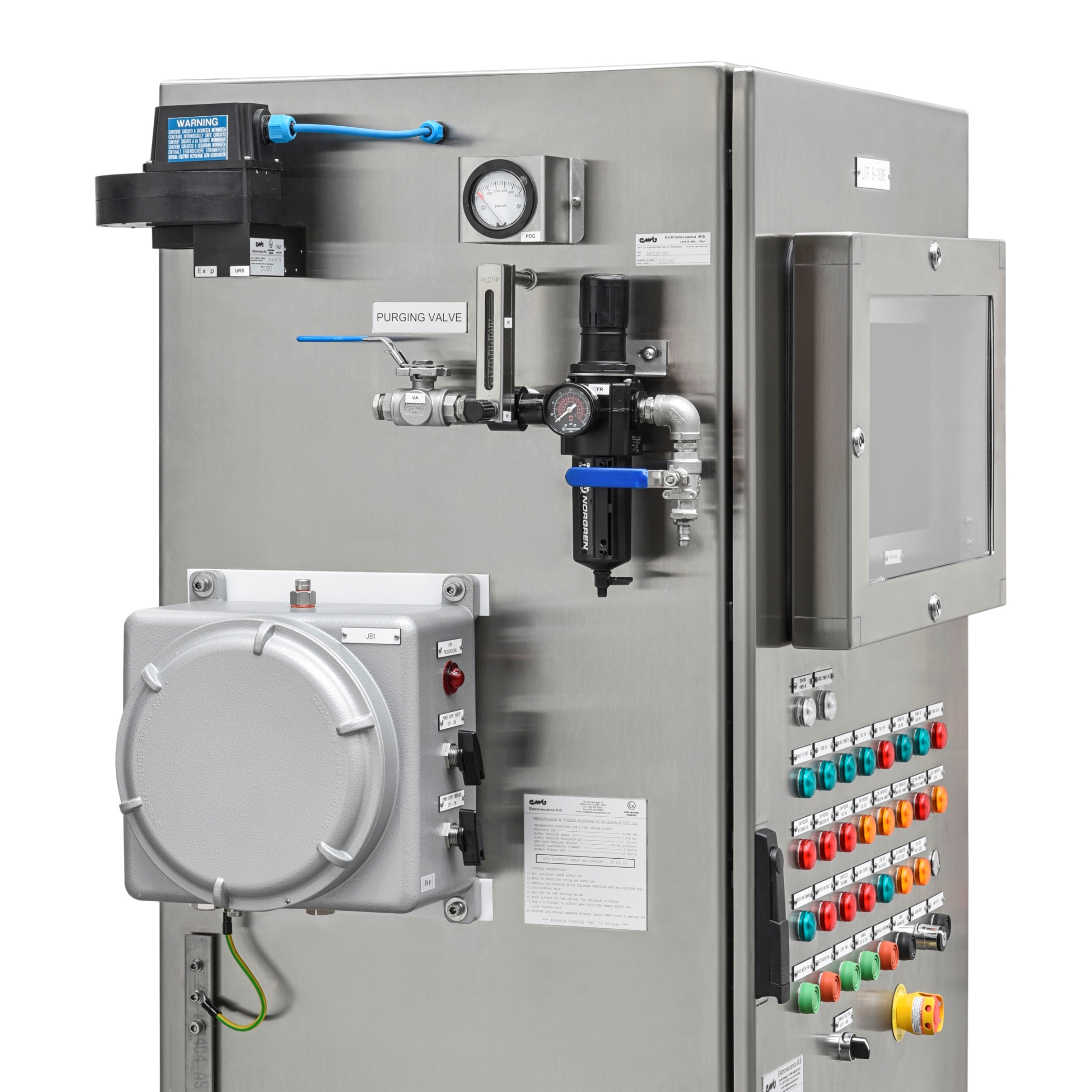
Each System consists of the following 3 Units:
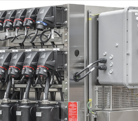
![]() UNIT 1: “Protective Gas Feeding” series MAG/…
UNIT 1: “Protective Gas Feeding” series MAG/…
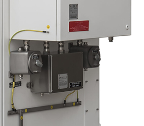
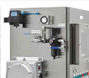
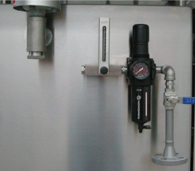
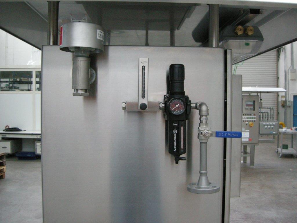
![]() UNIT 2: “Purging Gas Discharge and Pressure Control” series URS40/…
UNIT 2: “Purging Gas Discharge and Pressure Control” series URS40/…
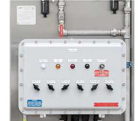
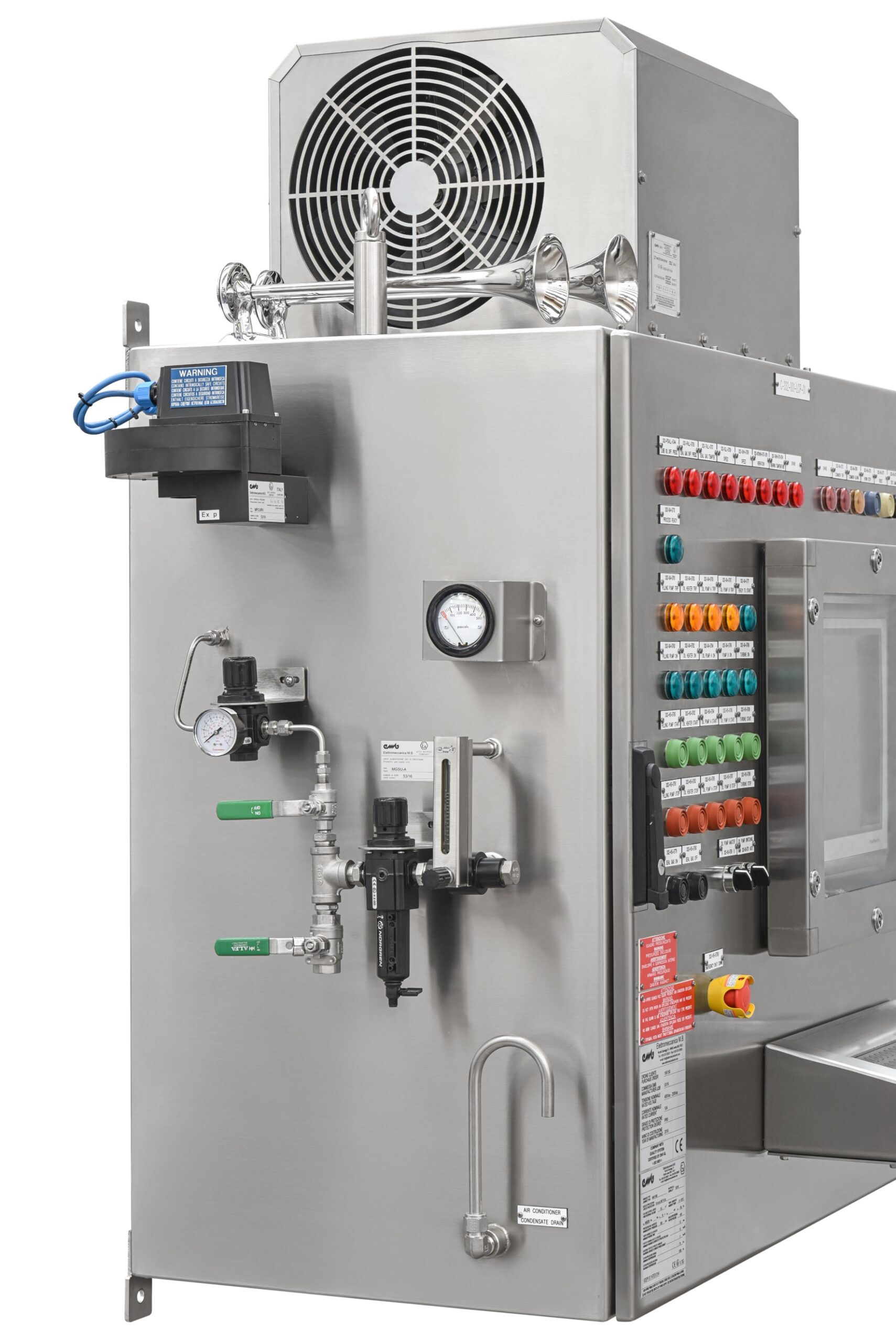
![]() UNIT 3: “Purging/Pressurization Control Logic” series MCP/…
UNIT 3: “Purging/Pressurization Control Logic” series MCP/…
and it can also be supplied separately, to be applied to an Ex p cabinet of another manufacturer
it is also possible to equip an our MAP cabinet with one of the many Systems existing on the market
However, these systems consist of pressurization control “Kits”, which generally make just 2 contacts available (i.e: “Purging Completed” and “Pressurization Failure”) without providing the user with specific instructions regarding the management of the power supplies and signals energized from the outside
In fact, the EN IEC 60079-2 Standard (Art. 7.1÷7.10 and Table 3) obligatorily requires that safety devices be integrated in the control system to allow the activation of the power supplies and signals energized from the outside, only after completion of the “Purging” operation
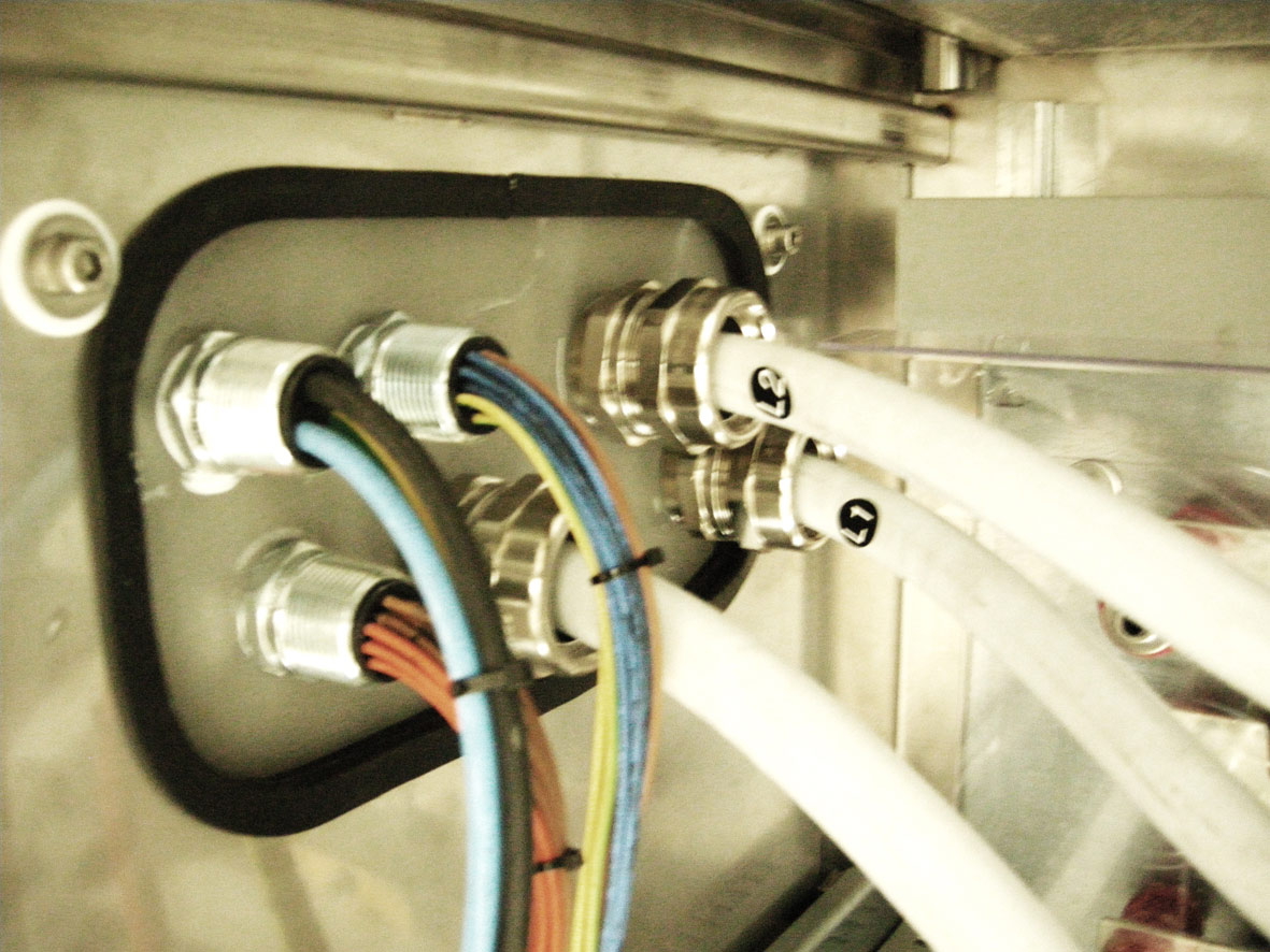
Therefore the possible Three-phase and/or Single-phase power supply voltages and any Analog/Digital signals and/or Data Transmission Lines (Fieldbus, Serial, Ethernet, Optical Fiber) energized from the outside, other than intrinsically safe, must be suitably interrupted remotely in a safe area, until purging is completed and, when this is not possible, suitable Switches and/or Contactors must be integrated into the control System to intercept the Power supplies and, if necessary, proper cutting Relays for the Signals powered from the outside
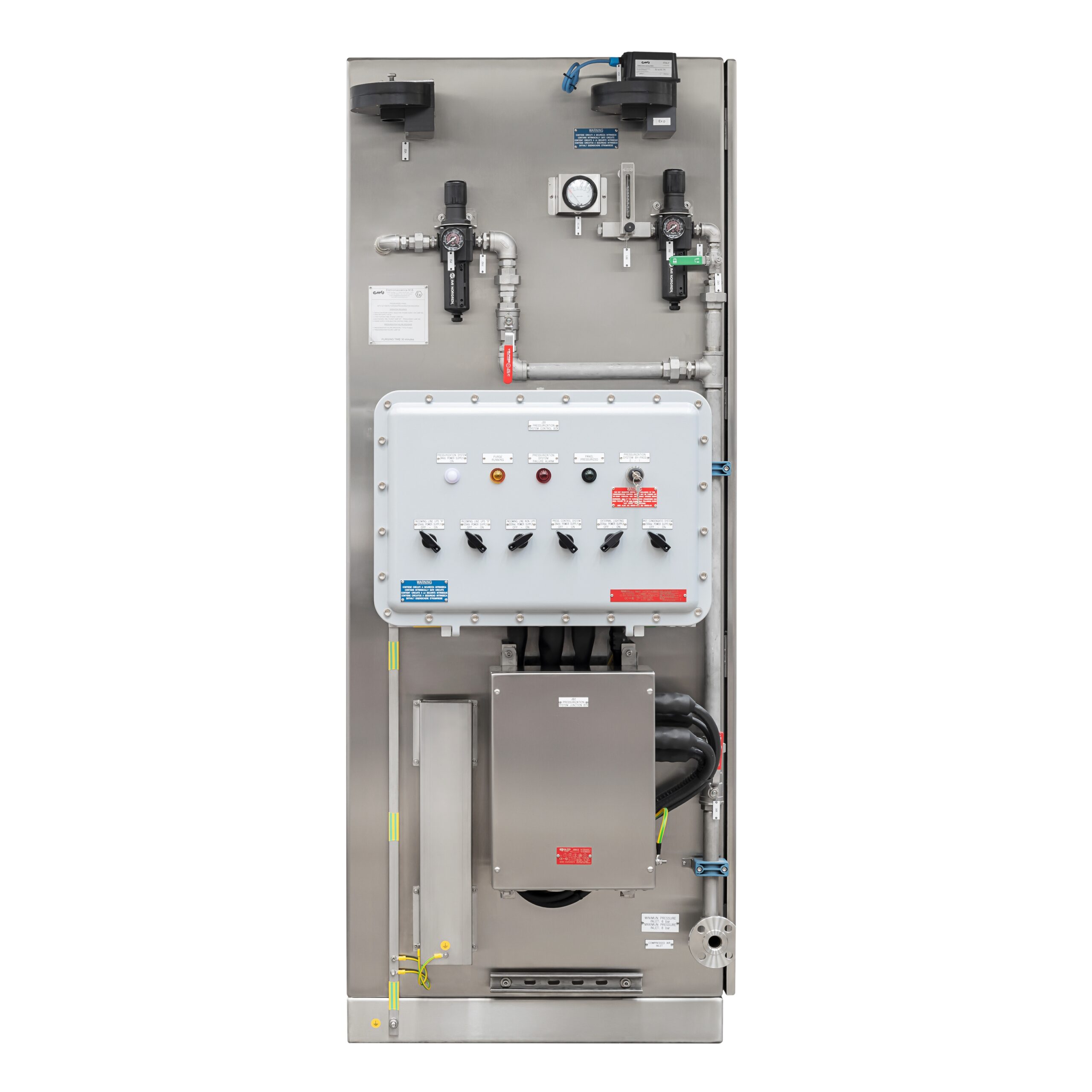
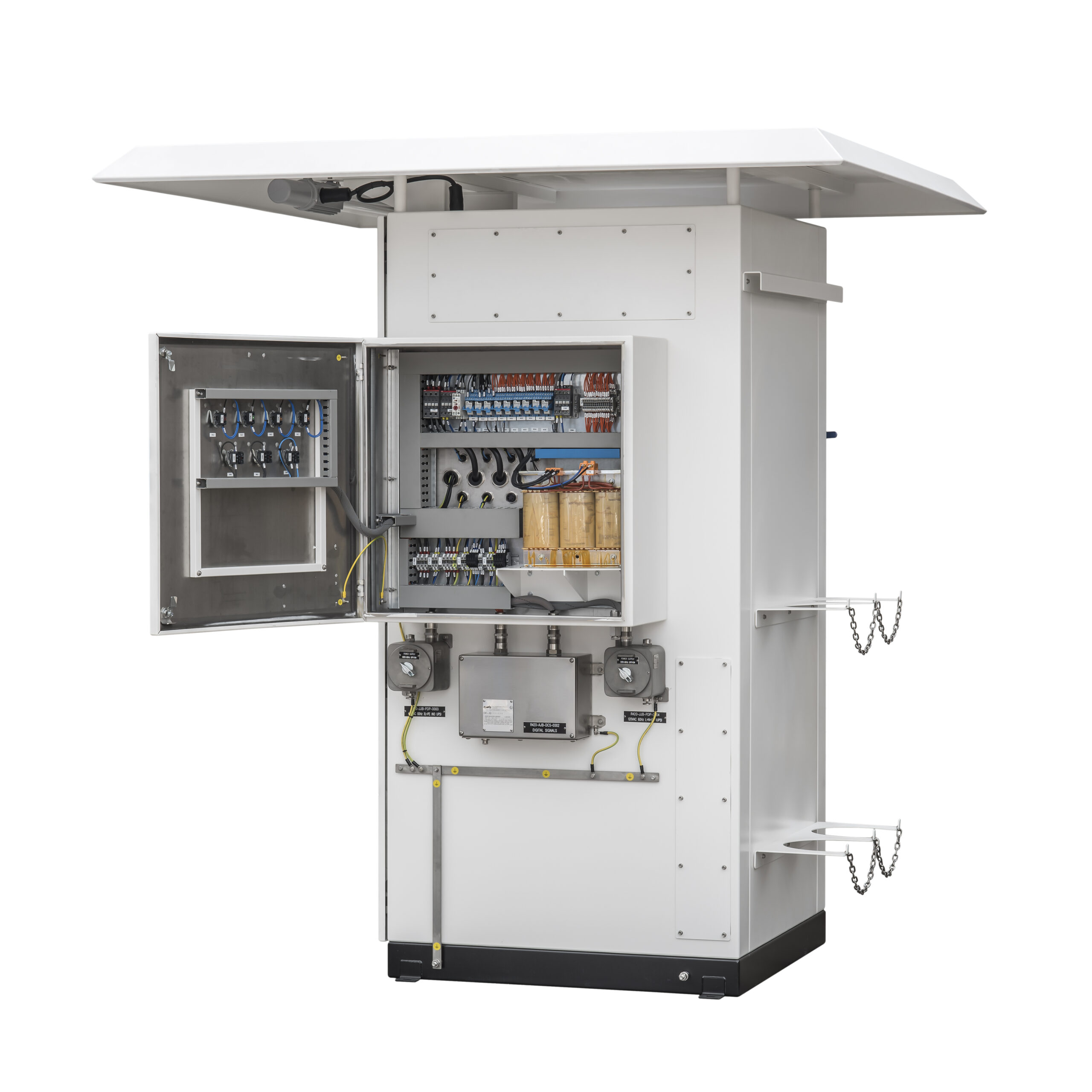
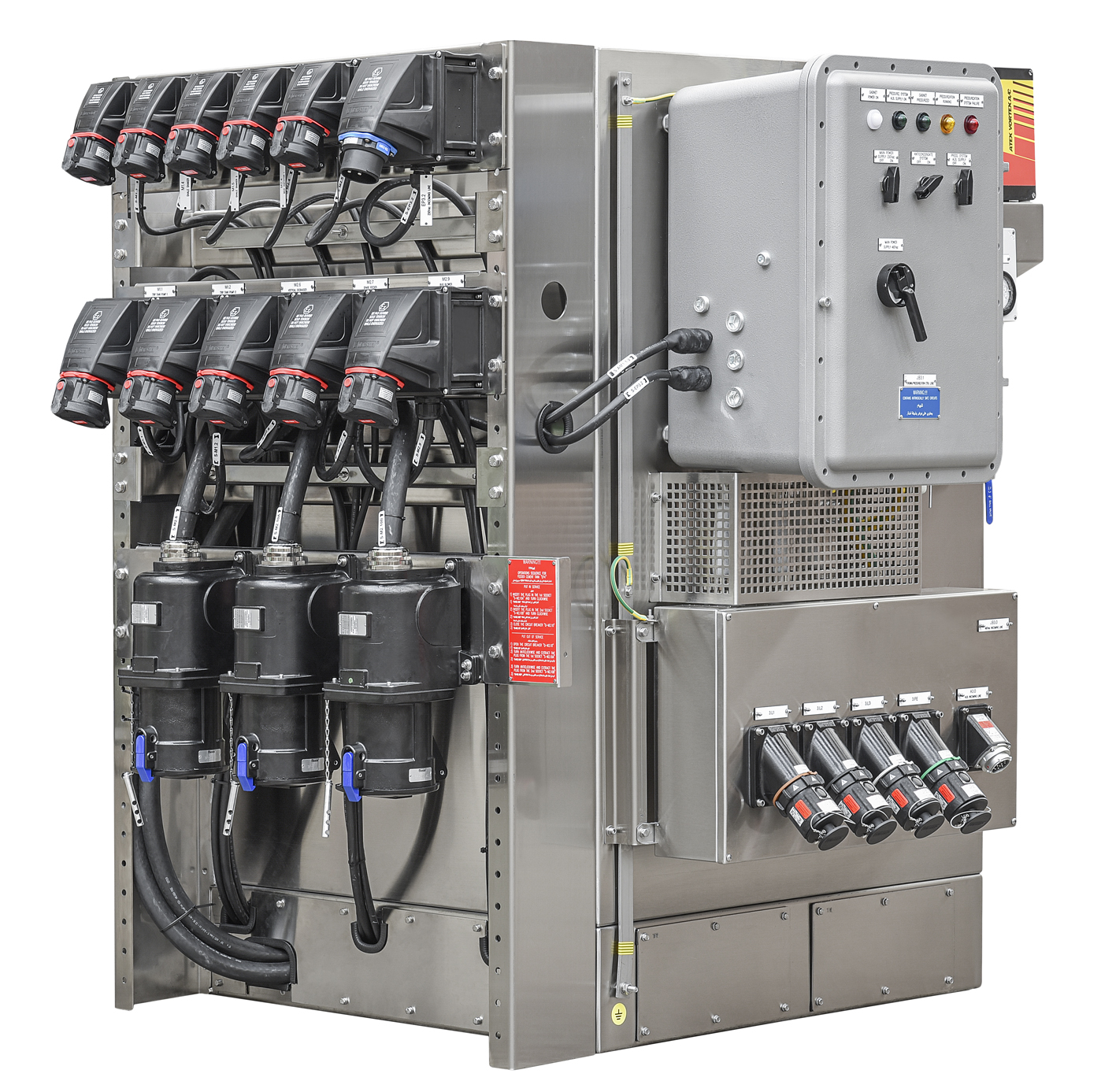
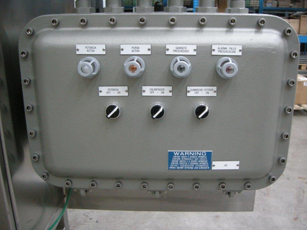
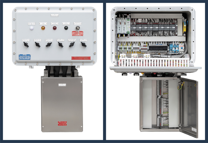
In our MSP series Systems, the components relating to the pressurization control logic (Unit 3) are generally housed inside an Ex d Enclosure, to which it may sometimes be necessary to assemble an Ex e enclosure for the terminal blocks
The Ex d Enclosure is sized to also contain all the additional necessary Devices, such as: Switches, Contactors and Cutting Relays, defined and evaluated by us from time to time in the estimate phase
The same enclosure can also be equipped with selector switches and Breakers, for the insertion of plants foreseen to complete the pressurized cabinet, such as:
![]() External lighting plant
External lighting plant
![]() Anti-condensation heating plant
Anti-condensation heating plant
![]() Air conditioning plant
Air conditioning plant
The User who decides to adopt the aforementioned “Kits”, equipped with only 2 auxiliary contacts, will run the risk of having to integrate all the other necessary Devices, housing them in Enclosure/s, with suitable type of protection (Ex d, Ex de , etc.) thus having to face major design difficulties in addition to the extra costs for unforeseen devices
Yet with reference to the obligation to avoid any presence of voltage inside a pressurized cabinet, until the purging is completed, we intend to report a Serious misunderstanding that can be found frequently, in installations in Zone 2.
Serious misunderstanding that can be found frequently, in installations in Zone 2
In the event that, after completing the purging and therefore with the cabinet in safe conditions, a fault occurs, the actions to be taken are dictated by the EN IEC 60079-14 Standard, art. 17.2.3.2.1 ÷ 3 and Table 19 which, for Zone 2 establishes the following:
“In locations requiring EPL ‘Gc’, an alarm is the minimum action that is recommended, if combined with immediate action by the operator to restore the pressurization or switch off the equipment”
Therefore we can conclude that, in Zone 2, in the event of a pressurization failure, the immediate interruption of the power supply is not expressly required
We have been able to note several times how this conclusion is acknowledged without taking into account what is mandatorily required first of all by EN IEC 60079-2, regarding purging and how an erroneous and extremely dangerous belief is often reached, such as:
“We are in Zone 2, the power cut is not mandatory and therefore we can freely power the cabinet without worrying about purging”
There is actually (always and exclusively in Zone 2) a real possibility of powering a pressurized cabinet without carrying out the “Purging” and yet in accordance with the EN IEC 60079-14 Standard which in Article 17.2.5 reads verbatim:
“If the concentration in the atmosphere within the enclosure and the associated ducting, for locations requiring EPL ‘Gc’, is well below the lower flammable limit (for example, 25% LEL ) purging may be omitted. Additionaly, gas detectors may be used to check whether the gas in the pressurized enclosure is flammable “
That is to say that in Zone 2 the instrumental verification of explosive atmosphere absence (≤ 25% of LEL) is allowed as an alternative to the purging phase
models
& EXAMPLES OF APPLICATION
The model of a Pressurization control System series MSP is defined by a basic code, composed as follow:
M: Manufacturer’s code (EMB)
SP: Pressurization control System
For the complete definition of the model, it is necessary to integrate the base code, with the following additional acronyms:
/A1: Automatic System for Pressurized Enclosures (Electrical-Instrumental Cabinets/Panels) according to EN IEC 60079-2, ATEX and IECEx certified, suitable for installation in Zone 1, “Ex ib pxb” type of protection
/A1-I: Automatic System for Pressurized Enclosures (Electrical-Instrumental Cabinets/Panels) according to EN IEC 60079-2, ATEX I M2 certified, suitable for Mine installation, “Ex ib pxb” type of protection
/A2: Automatic System for Pressurized Enclosures (Electrical-Instrumental Cabinets/Panels) according to EN IEC 60079-2, ATEX and IECEx certified, suitable for installation in Zone 2, “Ex ib pzc” type of protection
/M: Manual System for Pressurized Enclosures (Electrical-Instrumental Cabinets/Panels) according to EN IEC 60079-2, suitable for installation in Zone 2, “Ex ib pzc” type of protection
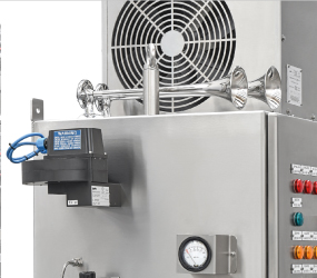
The following Application Examples show some of our most meaningful realizations of MSP Systems